01
CAD · ASSEMBLY · TECHNICAL DRAWINGMechanical Design
Evaluates geometry together with load path, material selection, assembly relationships and manufacturability.
MECHANICAL ENGINEERING PORTFOLIO // ACKENGINEERING WORKSHOP // TECHNICAL PORTFOLIO
Mechanical design.
Engineering analysis.
Technical verification.
Before I draw a part I want to know how it will be loaded, how it will be made and how it will be checked. I work across aerospace, mechanical design, manufacturing and quality.
Profile / Engineering Approach
Ahmet Can Kocaman is a mechanical engineer with experience in aerospace applications, mechanical design, manufacturing processes and quality control.
Using SolidWorks, CATIA, Autodesk Inventor and ANSYS Fluent, he carries out 3D modelling, technical drawing and CFD work together with material selection, load assessment and engineering calculations.
Evaluates geometry together with load path, material selection, assembly relationships and manufacturability.
Examines aerodynamic behaviour with numerical flow analysis and interprets the results together with boundary conditions and engineering assumptions.
Follows what the technical drawing corresponds to in production through tolerance, process conformity, quality control and traceability.
I write the requirement down first, then what I assumed. The calculation comes after that. If the result doesn't turn into geometry someone can actually make, the design isn't finished.
WORKING METHOD · REQUIREMENT · CALCULATION · MODEL · VERIFICATION
Selected Projects / Technical Outputs
This section presents geometry, load transfer, material selection, subsystem relationships, analysis assumptions and technical documentation together.
Design of the main landing gear consisting of axles, bogie beam, oleo-pneumatic shock strut and brake system.
The gallery presents the original 3D models and drawing sheets from the report directly. The main assembly, brake subsystem, kinematic positions and part relationships can be followed within the same technical narrative.
A good assembly should explain the load path, keep the subsystems readable and, once transferred to the technical drawing, preserve the component relationships consistently.
CONCEPTUAL DESIGN · AUTODESK INVENTOR · TECHNICAL DRAWINGThe work shows the design stages covering the fuselage frame, subsystem layout, outer shell geometry and alternative aircraft configurations.
Internal volume, component layout and outer surface geometry were examined as successive design stages.
Fuselage geometry and different aircraft layouts were assessed as separate design studies.
IMAGE NOTE The first two views isolate the helicopter and heavy-aircraft studies from the same project board. The other five views come from Ahmet Can Kocaman's CAD work.
Research work carried out on engineering calculations, project development and programming methods on the basis of NASA technical documents.
Ahmet Can's assembly video and original CAD drawings show the outer shell, connection geometry and component relationships directly from the project source.
The main video shows the assembly geometry in motion; the original drawings below present the components and technical views individually.
PLAY THE VIDEO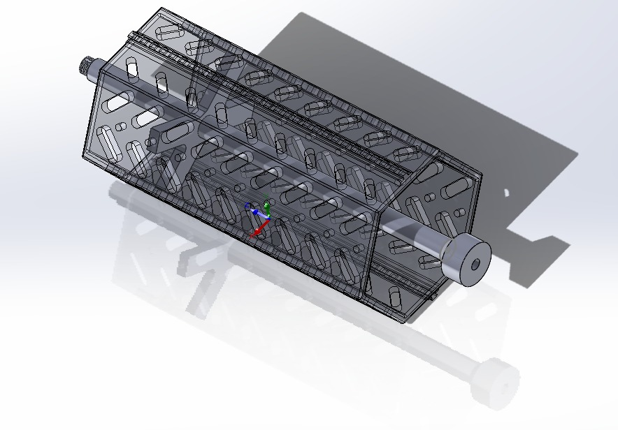 VIEW FULL SIZE ↗
Transparent CAD assembly view of the perforated outer shell, internal channel and central axis.
 VIEW FULL SIZE ↗
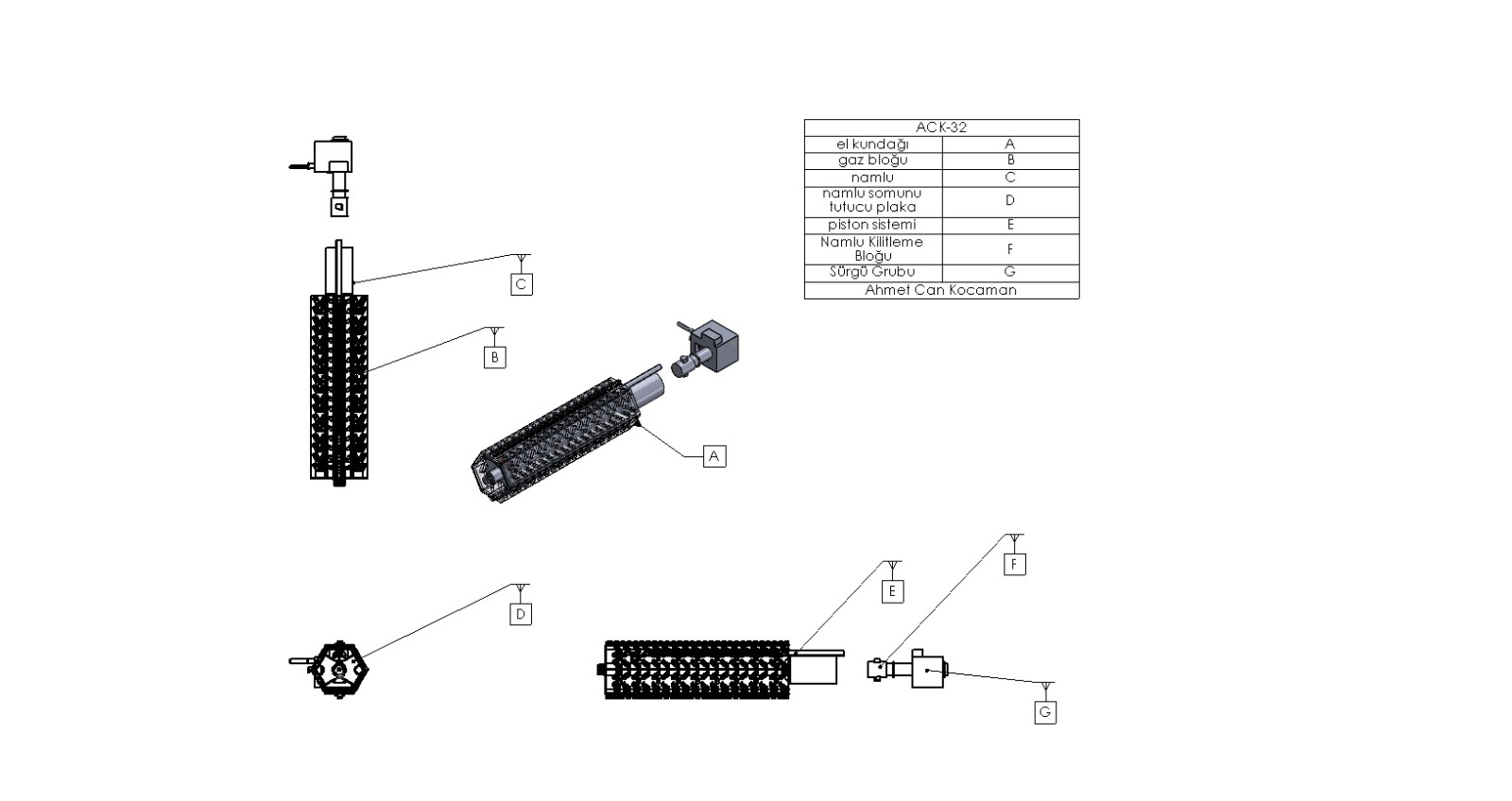
Assembly drawing presenting the principal components through separated views and part callouts.
 VIEW FULL SIZE ↗
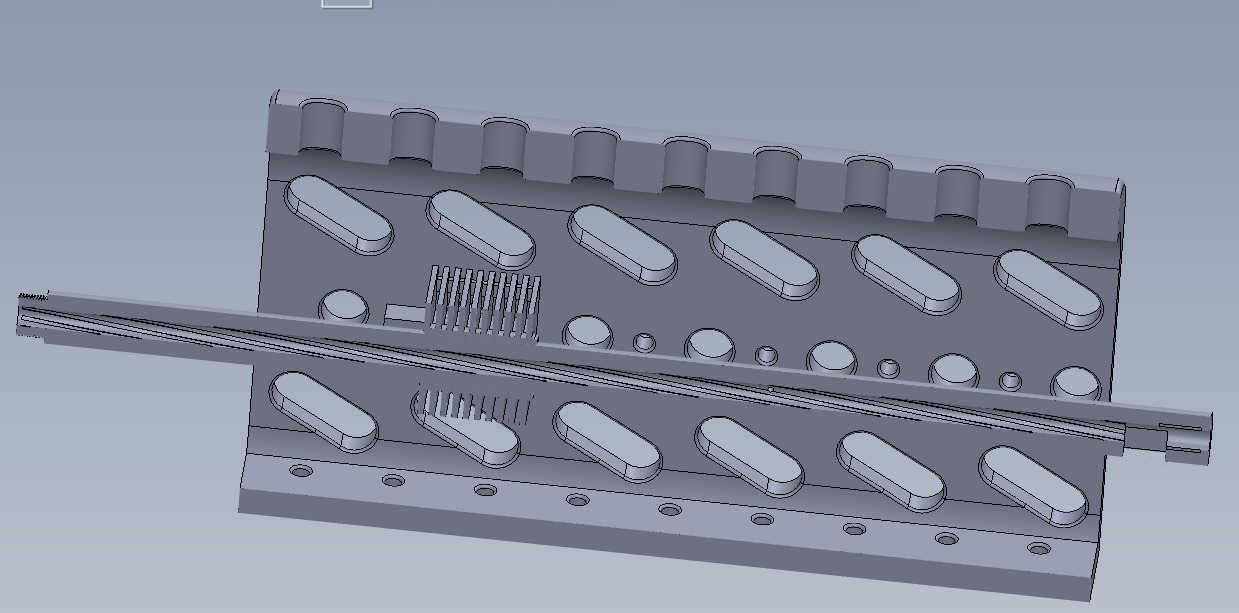
CAD view combining the repeating opening geometry with the central channel.
 VIEW FULL SIZE ↗
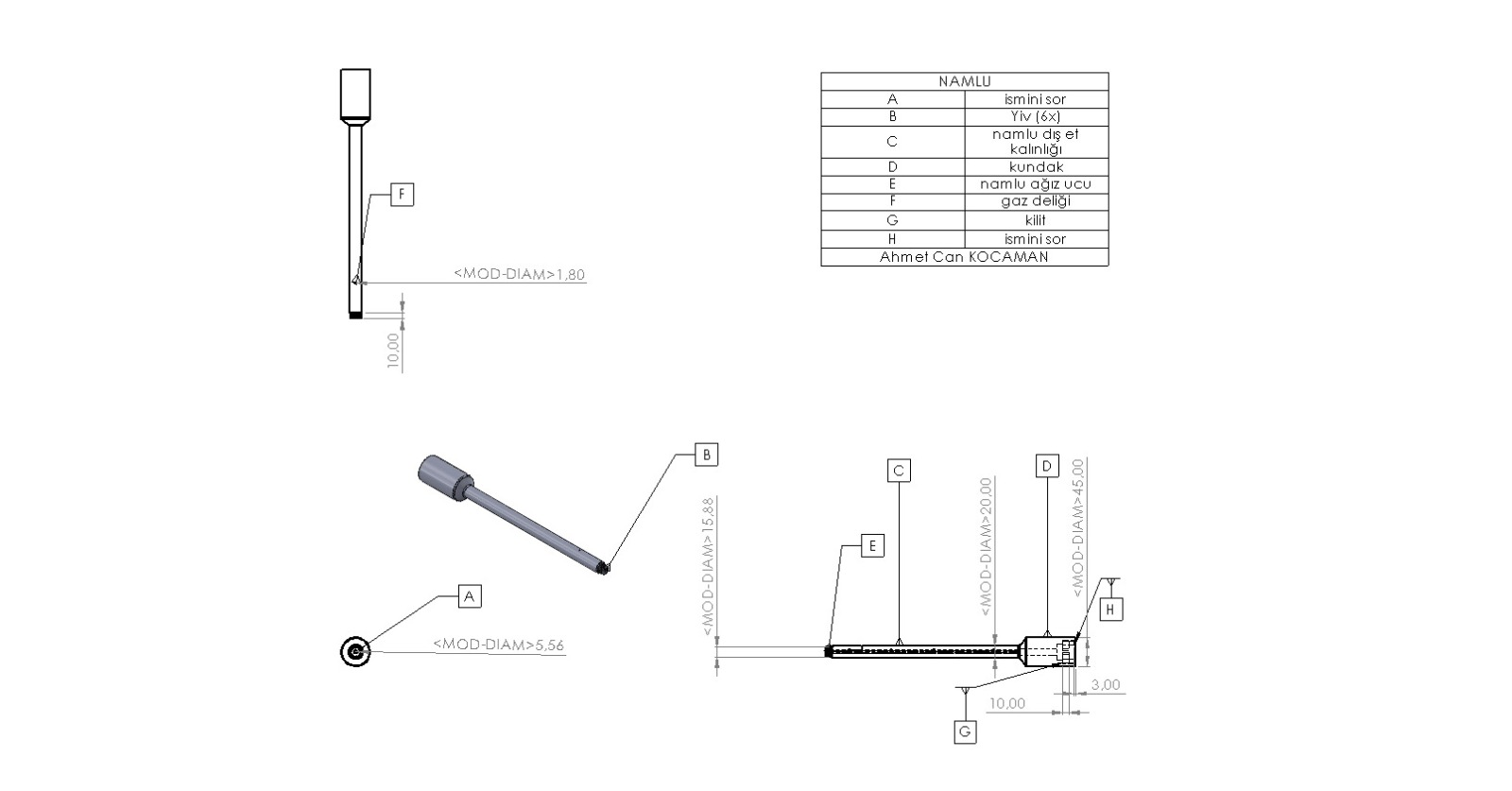
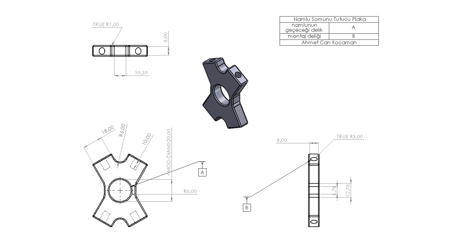
Documentation of the barrel geometry through multiple views, connection regions and drawing notes.
 VIEW FULL SIZE ↗
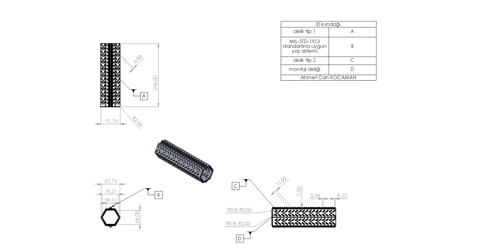
Technical drawing of the connection plate, central opening and mounting surfaces.
 VIEW FULL SIZE ↗
Section, side and isometric CAD drawing of the hexagonal outer shell.
The video and images in this section come from original CAD work uploaded by Ahmet Can Kocaman and have been prepared for legible, efficient web presentation.
Experience / Manufacturing and Design
In internship and project work he has taken part in technical drawing, manufacturing method, tolerance, material selection, quality control and regular reporting processes.
I work in mechanical design, aerospace applications, manufacturing and quality control. I don't judge a CAD model on its own — I judge it with the calculation, the drawing, the material and how it will be produced.
Contribution to the technical drawings and 3D models of aerospace components with CATIA; examination of manufacturing methods, technical requirements and quality control stages.
01Verification of the conformity of products to technical standards, quality criteria and manufacturing tolerances; nonconformity analysis and technical reporting.
02Technical project calculations, preparation and examination of test results; reporting of test, manufacturing and quality processes.
03Partly English-medium instruction; MÜDEK and EUR-ACE accreditation.
Technical Competencies
Uses CAD, analysis and programming tools in order to form design decisions, verify calculations and prepare technical outputs.
Quality management system fundamentals · Documentation · Internal audit · Risk-based process management
✓TSE2025
TSE2025
TSE2025
TSE2025
Achievements and Participation
Records relating to competition, congress and project work in robotics, mathematics, chemistry and aerospace are presented chronologically in this section.
Certificate of participation in a robotics competition in Chicago, USA with FRC Team 3390.
78th place in the Turkey ranking.
644th place worldwide in the University of Waterloo chemistry competition.
Advancing to the final design report stage two years in a row.
Oral presentation on the effect of axial compressor blade separation angles on pressure.
A technical result becomes verifiable when the input data, the assumptions, the calculation method and the acceptance criteria are recorded explicitly.
Contact
Write to me about a project, an internship, or something we could build together.